Attributes
Draw cracks
| type
|
bool
|
| default
|
True
|
|
|
Draw the extrapolated splines on the crack plane.
|
Crack plane indices
Like with the split plane feature, a user can create more than one plane with which to project a crack image through. By default there is a single crack node available. More can be added and are indexed starting at 0. Each crack plane index has its own instance of attributes, covered below, to allow for individual adjustment of attributes on a per plane basis.
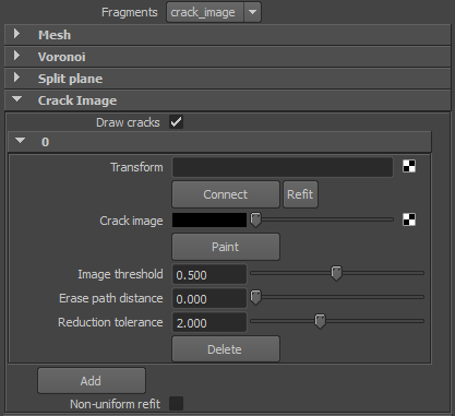
The Attribute Editor example below shows that the current node has 3 crack image planes. The first one (0) is expanded to illustrate the available attributes for each crack image plane.

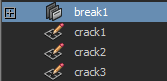
When connected, each of these nodes can be found in the Outliner. By default the naming convention is "crack#".
Transform
| type
|
string
|
|
|
Name of the sketchPlane node assigned to the current index. When a new index is added it does not yet have a crack node (sketchPlane) assigned. Clicking the Connect button will generate the node. If, at any time, the source geometry is scaled the Refit button will scale to the largest bounding box axis.
|
Crack image
| type
|
color
|
|
|
Attribute that the input image will be connected to. On a new crack image node there won't yet be in image connect. Clicking the Paint button will immediately put in you into paint mode.
|
Image threshold
| type
|
float
|
| default
|
0.5
|
| minimum
|
0.0
|
| maximum
|
1.0
|
|
|
Pixel value.
|
Erase path distance
| type
|
float
|
| default
|
0.0
|
| minimum
|
0.0
|
|
|
Erase paths shorter than this distance in pixels.
|
Reduction tolerance
| type
|
float
|
| default
|
2.0
|
| minimum
|
0.0
|
|
|
Merge distance in pixels.
|
Non-uniform refit
| type
|
bool
|
| default
|
False
|
|
|
TODO: description
|
Buttons
Connect
Refit
Paint
Delete
Add


